ZuluSCSI Operations Guide
This page is still a work in progress. Sections marked with a  icon are still in the process of being edited and finalized.
Setting Up Your ZuluSCSI
Unboxing
When you first receive your ZuluSCSI, depending on the options you ordered, you should receive the following:
- ZuluSCSI RP2040 Compact, ZuluSCSI Blaster, or ZuluSCSI 1.2 board
- Plastic board carrier
- 2x ¼" 4-40 screws
- microSD card or full-size SD card
- DAC board (ZuluSCSI Blaster only)
Board Overview
Take a moment to identify the various parts of the board as shown below, based on the type of board you have.
| ZuluSCSI RP2040 Compact | ZuluSCSI Blaster RP2350B | ZuluSCSI 1.2 |
|---|---|---|

|

|

|
- 4-pin Molex floppy power connector: Run a standard Molex 4-pin power cable to this port. If your system power supply has only the larger style, get an adapter cable to switch it to the smaller size (the same size as that found on a 3½" floppy disk drive; see below).
- 50-pin male IDC connector: Plug your SCSI bus cable into this. The connector is keyed, but some SCSI cables lack the key, so make sure that the red stripe on the cable lines up with the little arrow embossed into the connector itself.
- Activity LED: Flashes in sync with drive access, also used to indicate status conditions as described later
- Eject button: Performs a hardware eject for optical drives. Some operating systems will need this after dismounting an image from the system to register that the drive door is closed.
- BOOTLDR button: Used in the firmware flashing process; see below.
- USER button: Reserved for future use.
- Termination and Initiator jumpers (Compact only): Populate these footprints with standard 0.1" header, solder them down, and then use a standard jumper cap to switch on the ZuluSCSI Compact's termination capabilities or enable initiator mode.
- DIP Switch Block (ZuluSCSI Blaster only): Used to enable initiator mode, termination, or debug mode.
- I2S Accessory Header (ZuluSCSI Blaster only): If you purchased the optional I2S DAC for CD audio capability, insert it here.
- Device type selector switch (ZuluSCSI 1.2 only): Use this rotary switch to select the type of device the ZuluSCSI is meant to emulate here. This switch is only active when switch 2 on the Settings DIP switch block is set to off.
- SCSI ID Dip Switch (ZuluSCSI 1.2 only): Use this set of switches to set the device's SCSI ID.
- Device Settings Switch block (ZuluSCSI 1.2 only): Use these switches to control termination, debug mode, "quirks" mode (for some Macintosh devices) and whether the entirety of the SD card is exposed as a single block device, or whether the device reads the SD card for image files and emulates multiple devices dependent on filename (as with other ZuluSCSI devices).
Molex power connector
Make sure that your power connection uses a 3½" floppy power connector, not the larger drive connector used on full-size optical drives, hard drives, and the like.

|
.png)
|

|
.png)
|
|---|---|---|---|
| ✅ 3½" connector | ❌ 5¼" connector | ||
If your host system only has the 5¼" connectors, you'll need to either purchase or make an adapter cable. Making an adapter cable requires the following parts:
- 4× 5¼ male pins: TE Connectivity P/N 60620-1
- 1× 5¼ male housing: TE Connectivity P/N 1-480426-0
- 4× 3½ female sockets: TE Connectivity P/N 170262-1
- 1× 3½ female housing: TE Connectivity P/N 171822-4
When making the cables, use 20-gauge wire. If you're crimping a splitter cable, it's also possible to use 18-gauge wire on the 5¼ side going to the female plug, and then crimp the larger wire going into the male splitter side together with 22 or 24-gauge wire going to the 3½ side. Crimping the cables can be done with standard tools found on Amazon, such as the IWISS SN-025.
DIP Switch Configuration
ZuluSCSI Blaster or ZuluSCSI RP2040 Compact
- Switch 1: Turn Initiator mode on or off.
- On the RP2040 Compact, this is controlled by the jumper at
J310on the board in the lower right.
- On the RP2040 Compact, this is controlled by the jumper at
- Switch 2: Debug log disable/enable. If this switch is ON, the device will automatically write out a detailed debug log to
zululog.txton the SD card as long as the device is powered on. Additionally, if you have a USB cable plugged into the port on the device with this switch on, it will also print the debug log over the cable via the microcontroller's internal serial connection.- On the RP2040 Compact, this is controlled by setting
Debug = 1in thezuluscsi.inifile on the SD card itself.
- On the RP2040 Compact, this is controlled by setting
- Switch 3: Enable or disable SCSI termination as needed.
- On the RP2040 Compact, this is controlled by the jumper at
J311in the center of the board.
- On the RP2040 Compact, this is controlled by the jumper at
ZuluSCSI 1.2
If you have a ZuluSCSI 1.2, the block of four DIP switches at SW301 control various aspects of how the device responds in the system:
- Switch 1: Toggle Macintosh "Quirks" mode. On some legacy Macs, it helps if the device responds with specific things when the system calls upon it during a fresh installation. If your Mac responds erratically or doesn't behave properly with the device in the system, try turning this switch ON before anything else.
- Switch 2: Direct/Raw mode vs. standard mode. If this switch is left in its default OFF position, then the entire SD card is exposed to the system as a single block device and allows your SCSI interface card to manage it, based on the settings of
SW403andSW404.- The block of three DIP switches at
SW403are used for setting your SCSI ID. If all three switches are off, the board's SCSI ID is 0. Turn switch 1 on to add 1 to the device ID, switch 2 to add 2, and switch 3 to add 4. If all three are on, the SCSI ID is 7. - The rotary switch at
SW404controls how the ZuluSCSI responds to your SCSI interface card when it queries it. Each position on the switch causes it to respond as a different device and will register differently:- Position 0 (straight up): Hard disk
- Position 1: Optical drive
- Position 2: Floppy disk
- Position 3: Other generic removable block device
- Position 4: Magneto-optical disk drives
- Position 5: Seagate ST32430N Hawk HDD
- Position 6: Sequential magnetic tape drives
- Positions 7, 8, 9: Reserved
- The block of three DIP switches at
Activity LED
The Activity LED will flash normally during disk access, however, in certain specific failure modes or status changes, you will see it flashing with a pattern.
- 1 fast blink, at boot time: Image file loaded successfully
- 3 fast blinks: No valid images found on SD card
- 5 fast blinks: SD card is present, but is not responding
- Morse code pattern: Firmware crash. The particular pattern will indicate where the crash occurred.
- If a firmware crash occurs, it will also try to save information to the file
zuluerr.txton the SD card.
- If a firmware crash occurs, it will also try to save information to the file
SD Card Preparation and Use
Format your SD card with either the FAT32 or exFAT filesystems. If you intend to use an SD card larger than 4 GB in size, you must format the card using exFAT as the FAT32 filesystem cannot support individual files larger than 4 GB. The card can be of any size as long as the card has an SDHC or SDXC classification badge. There is no upper limit for how large the card is (the maximum size supported by the SDXC specification is 2 TB, for example) however, you may notice slowdowns on the device if you store large numbers of individual files of any size in any single folder.
The device will not read SD cards formatted using the GPT (GUID Partition Map) method. If you try to use a card formatted with this method, the Activity LED will blink 5 times with the card inserted, indicating that the card's presence is being detected, but that it is unresponsive.
To make use of your ZuluSCSI, place disk image files in the root folder of the SD card and name them based upon the device and SCSI ID you want them to occupy on the bus. Your filename should follow the format xxy.img, where x is a two-character code representing the device to be emulated, and y is a number representing the SCSI ID number you intend the device to take, from 0 to 7.
If you're emulating other devices on the ZuluSCSI, use the following two-character prefixes for your images depending on the device you want it to be:
HD: Hard diskCD: Optical driveFD: Floppy diskMO: Magneto-opticalRE: Generic removable deviceTP: Sequential tapeZP: Zip-100 or Zip-250 drive
For example, if you want the ZuluSCSI to emulate a three-device system containing two hard disks at IDs 3 and 4 and a single optical drive at ID 6, copy your images over and name them HD3.img, HD4.img, and CD6.iso inside the root folder of the card.
![]() Images can also be stored in folders, but will not be accessible by the device unless you name the folder using the format described above. This is handy when you want to cycle images on a particular device, like floppy disks or CDs.
Images can also be stored in folders, but will not be accessible by the device unless you name the folder using the format described above. This is handy when you want to cycle images on a particular device, like floppy disks or CDs.
Creating empty disk images
The ZuluSCSI can also create empty disk images for you. To do this, create a zero-length text file named using the following format:
Create <size> <device type><SCSI ID>.txt
<size> should be a value in the format xxxY, where xxx is a number and Y is a letter representing the magnitude of that number. For example, 20M would be 20 megabytes, 20G would be 20 gigabytes, 20K would be 20 kilobytes, etc.
<device type> is a two-letter code corresponding to the device type desired above. Currently, only rewritable image types are supported, meaning the HD, FD, MO, TP, and ZP device types are supported.
<SCSI ID> is a number from 0 to 7 indicating the SCSI ID number that the device should occupy when the image is fully written and ready.
An example filename to create a 1024-megabyte hard disk drive at SCSI ID 4 would be Create 1024M HD4.txt.
Copy the text file to the root folder of your SD card, place the card in the ZuluSCSI and turn it on. The ZuluSCSI will initialize and mount any existing images first, and then get to work creating your empty image file. The access LED will flash continuously during image creation and, in the case of very large images, can take some time to complete.
Creating zero-length text files
On Windows, use a program like Notepad or Notepad++, create a new file, and immediately save it on the SD card with the desired filename.
On Linux-based machines or Macs running OS X, open a Terminal window, and then type touch <filename.txt> and then copy the resulting file to the SD card.
Updating the Firmware
New firmware releases can be obtained by visiting the Github page for the project. The most recent firmware will be listed at the top with a green "Latest" badge. You can update the firmware in three different ways.
Using a ZIP file
ZuluSCSI boards running firmware v2024.12.03 or later can be updated by simply placing a ZIP file downloaded from the Github releases page.
Download the ZuluSCSI-FW_YYYY-MM-DD-universalFW.zip file from the repository (where YYYY, MM, and DD represent the year, month, and date of release) directly to the SD card you're using, place the card back into the ZuluSCSI and turn on the system. The ZuluSCSI will take care of extracting and applying the firmware update on its own and, unless the system's boot time is exceptionally fast, the firmware update should apply in time for the system BIOS to catch the change.
Using the SD card
The ZuluSCSI can update itself when it's initially powered on. You'll need to have access to the device so you can remove its SD card.
- Power down the system that the ZuluSCSI is attached to and remove its SD card.
- Attach the SD card to the computer where you'll download the update.
- From the Github page, download the latest firmware file with a .BIN extension.
- Copy the downloaded .BIN file to the root folder of the SD card and rename it as
ZuluSCSI.bin. - Dismount the SD card from the computer, and reinsert the SD card into the ZuluSCSI.
- Power the system back on. The ZuluSCSI will automatically begin the firmware update process, which takes about one second. If the system has to boot to the ZuluSCSI and its startup is particularly quick, you may need to reset the computer once to allow the firmware update process to complete on the ZuluSCSI so it can become ready.
- When the firmware update process finishes, the ZuluSCSI will delete the update file and continue on to normal operation.
Using the BOOTLDR button

If you have physical access to the device and a way to plug the MicroUSB or USB-C port into a host computer, this is the traditional way to update RP2040 and RP2350B-based devices.
- Power down the system the ZuluSCSI is attached to, and if necessary, unplug it from its cabling.
- From the Github page, download the latest firmware file with a .UF2 extension.
- Attach a MicroUSB cable to the device you'll be uploading the firmware from.
- While holding down the BOOTLDR button on the ZuluSCSI, attach the other end of the cable to the MicroUSB port on the ZuluSCSI.
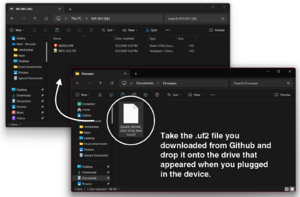
Copy the UF2 file to the device. - A Windows Explorer window may appear with a drive called
RPi-RP2. If it doesn't, open a Windows Explorer window and look for a drive with this name. - Copy the .UF2 file you downloaded to the root folder of the drive that appeared when you plugged in the ZuluSCSI.
- The
RPi-RP2window should close on its own once the copy completes. When the device disconnects on its own, the firmware update process is complete. - Disconnect the USB cables and reattach the ZuluSCSI to its host, if you removed it in step 1.

Troubleshooting
Some simple things to check before you dive deeper:
- Make sure that there are no devices contending for the same ID number on the bus. Typically, the host device on a system is identified as ID 7, so avoid using ID 7 where possible.