ZuluSCSI Operations Guide: Difference between revisions
Updating documentation for ZSCSI Blaster |
|||
| Line 1: | Line 1: | ||
= This page | = This page is still a work in progress. Sections marked with a [[File:Warning.png|frameless|32x32px]] icon are still in the process of being written. = | ||
== Setting Up Your ZuluSCSI == | == Setting Up Your ZuluSCSI == | ||
=== Unboxing === | === Unboxing === | ||
When you first receive your ZuluSCSI, depending on the options you ordered, you should receive the following: | When you first receive your ZuluSCSI, depending on the options you ordered, you should receive the following: | ||
* ZuluSCSI RP2040 Compact board | * ZuluSCSI RP2040 Compact, ZuluSCSI Blaster, or ZuluSCSI 1.2 board | ||
* | * Plastic board carrier | ||
* 2x ¼" 4-40 screws | * 2x ¼" 4-40 screws | ||
* microSD card | * microSD card or full-size SD card | ||
* DAC board (ZuluSCSI Blaster only) | |||
* DAC board | |||
== Board Overview == | == Board Overview == | ||
Take a moment to identify the various parts of the board as shown below. | Take a moment to identify the various parts of the board as shown below, based on the type of board you have. | ||
[[File: | {| class="wikitable" | ||
|+ | |||
* '''4-pin Molex floppy power connector:''' Run a standard Molex 4-pin power cable to this port. If your system power supply has only the larger style, get an adapter cable to switch it to the smaller size (the same size as that found on a 3½" floppy disk drive). | !ZuluSCSI RP2040 Compact | ||
* ''' | !ZuluSCSI Blaster RP2350B | ||
!ZuluSCSI 1.2 | |||
|- | |||
|[[File:ZSCSI compact labeled.png|frameless]] | |||
|[[File:ZSCSI Blaster labeled.png|frameless]] | |||
|[[File:ZSCSI1.2 Labeled.png|frameless]] | |||
|} | |||
* '''4-pin Molex floppy power connector:''' Run a standard Molex 4-pin power cable to this port. If your system power supply has only the larger style, get an adapter cable to switch it to the smaller size (the same size as that found on a 3½" floppy disk drive; see below). | |||
* '''50-pin male IDC connector:''' Plug your SCSI bus cable into this. The connector is keyed, but some SCSI cables lack the key, so make sure that the red stripe on the cable lines up with the little arrow embossed into the connector itself. | |||
* '''Activity LED:''' Flashes in sync with drive access, also used to indicate status conditions as described later | * '''Activity LED:''' Flashes in sync with drive access, also used to indicate status conditions as described later | ||
* '''Eject button:''' Performs a hardware eject for optical drives. Some operating systems will need this after dismounting an image from the system to register that the drive door is closed. | * '''Eject button:''' Performs a hardware eject for optical drives. Some operating systems will need this after dismounting an image from the system to register that the drive door is closed. | ||
* ''' | * '''BOOTLDR button:''' Used in the firmware flashing process; see below. | ||
* '''USER button:''' Reserved for future use. | |||
* '''Termination and Initiator jumpers (Compact only):''' Populate these footprints with standard 0.1" header, solder them down, and then use a standard jumper cap to switch on the ZuluSCSI Compact's termination capabilities or enable initiator mode. | |||
* '''DIP Switch Block (ZuluSCSI Blaster only):''' Used to enable initiator mode, termination, or debug mode. | |||
* '''I<sup>2</sup>S Accessory Header (ZuluSCSI Blaster only):''' If you purchased the optional I<sup>2</sup>S DAC for CD audio capability, insert it here. | |||
* '''Device type selector switch (ZuluSCSI 1.2 only):''' Use this rotary switch to select the type of device the ZuluSCSI is meant to emulate here. This switch is only active when switch 2 on the Settings DIP switch block is set to '''off.''' | |||
* '''SCSI ID Dip Switch (ZuluSCSI 1.2 only):''' Use this set of switches to set the device's SCSI ID. | |||
* '''Device Settings Switch block (ZuluSCSI 1.2 only):''' Use these switches to control termination, debug mode, "quirks" mode (for some Macintosh devices) and whether the entirety of the SD card is exposed as a single block device, or whether the device reads the SD card for image files and emulates multiple devices dependent on filename (as with other ZuluSCSI devices). | |||
== Molex power connector == | == Molex power connector == | ||
| Line 53: | Line 58: | ||
== DIP Switch Configuration == | == DIP Switch Configuration == | ||
* '''Switch 1:''' Turn | === ZuluSCSI Blaster or ZuluSCSI RP2040 Compact === | ||
* '''Switch 2 | * '''Switch 1:''' Turn Initiator mode on or off. | ||
** On the RP2040 Compact, this is controlled by the jumper at <code>J310</code> on the board in the lower right. | |||
* '''Switch 2:''' Debug log disable/enable. If this switch is ON, the device will automatically write out a detailed debug log to <code>zululog.txt</code> on the SD card as long as the device is powered on. Additionally, if you have a USB cable plugged into the port on the device with this switch on, it will also print the debug log over the cable via the microcontroller's internal serial connection. | |||
** On the RP2040 Compact, this is controlled by setting <code>Debug = 1</code> in the <code>zuluscsi.ini</code> file on the SD card itself. | |||
* '''Switch 3:''' Enable or disable SCSI termination as needed. | |||
** On the RP2040 Compact, this is controlled by the jumper at <code>J311</code> in the center of the board. | |||
== | === ZuluSCSI 1.2 === | ||
If you have a ZuluSCSI 1.2, the block of '''four''' DIP switches at <code>SW301</code> control various aspects of how the device responds in the system: | |||
* '''Switch 1:''' Toggle Macintosh "Quirks" mode. On some legacy Macs, it helps if the device responds with specific things when the system calls upon it during a fresh installation. If your Mac responds erratically or doesn't behave properly with the device in the system, try turning this switch ON before anything else. | |||
* '''Switch 2:''' Direct/Raw mode vs. standard mode. If this switch is left in its default OFF position, then the entire SD card is exposed to the system as a single block device and allows your SCSI interface card to manage it, based on the settings of <code>SW403</code> and <code>SW404</code>. | |||
** The block of '''three''' DIP switches at <code>SW403</code> are used for setting your SCSI ID. If all three switches are off, the board's SCSI ID is 0. Turn switch 1 on to add 1 to the device ID, switch 2 to add 2, and switch 3 to add 4. If all three are on, the SCSI ID is 7. | |||
** The rotary switch at <code>SW404</code> controls how the ZuluSCSI responds to your SCSI interface card when it queries it. Each position on the switch causes it to respond as a different device and will register differently: | |||
*** Position 0 (straight up): Hard disk | |||
*** Position 1: Optical drive | |||
*** Position 2: Floppy disk | |||
*** Position 3: Other generic removable block device (ZIP drives, Jaz drives, etc.) | |||
*** Position 4: Magneto-optical disk drives | |||
*** Position 5: Seagate ST32430N Hawk HDD | |||
*** Position 6: Tape drives | |||
*** Positions 7, 8, 9: Reserved | |||
== Activity LED == | == Activity LED == | ||
Revision as of 17:05, 15 April 2025
This page is still a work in progress. Sections marked with a  icon are still in the process of being written.
Setting Up Your ZuluSCSI
Unboxing
When you first receive your ZuluSCSI, depending on the options you ordered, you should receive the following:
- ZuluSCSI RP2040 Compact, ZuluSCSI Blaster, or ZuluSCSI 1.2 board
- Plastic board carrier
- 2x ¼" 4-40 screws
- microSD card or full-size SD card
- DAC board (ZuluSCSI Blaster only)
Board Overview
Take a moment to identify the various parts of the board as shown below, based on the type of board you have.
| ZuluSCSI RP2040 Compact | ZuluSCSI Blaster RP2350B | ZuluSCSI 1.2 |
|---|---|---|

|

|

|
- 4-pin Molex floppy power connector: Run a standard Molex 4-pin power cable to this port. If your system power supply has only the larger style, get an adapter cable to switch it to the smaller size (the same size as that found on a 3½" floppy disk drive; see below).
- 50-pin male IDC connector: Plug your SCSI bus cable into this. The connector is keyed, but some SCSI cables lack the key, so make sure that the red stripe on the cable lines up with the little arrow embossed into the connector itself.
- Activity LED: Flashes in sync with drive access, also used to indicate status conditions as described later
- Eject button: Performs a hardware eject for optical drives. Some operating systems will need this after dismounting an image from the system to register that the drive door is closed.
- BOOTLDR button: Used in the firmware flashing process; see below.
- USER button: Reserved for future use.
- Termination and Initiator jumpers (Compact only): Populate these footprints with standard 0.1" header, solder them down, and then use a standard jumper cap to switch on the ZuluSCSI Compact's termination capabilities or enable initiator mode.
- DIP Switch Block (ZuluSCSI Blaster only): Used to enable initiator mode, termination, or debug mode.
- I2S Accessory Header (ZuluSCSI Blaster only): If you purchased the optional I2S DAC for CD audio capability, insert it here.
- Device type selector switch (ZuluSCSI 1.2 only): Use this rotary switch to select the type of device the ZuluSCSI is meant to emulate here. This switch is only active when switch 2 on the Settings DIP switch block is set to off.
- SCSI ID Dip Switch (ZuluSCSI 1.2 only): Use this set of switches to set the device's SCSI ID.
- Device Settings Switch block (ZuluSCSI 1.2 only): Use these switches to control termination, debug mode, "quirks" mode (for some Macintosh devices) and whether the entirety of the SD card is exposed as a single block device, or whether the device reads the SD card for image files and emulates multiple devices dependent on filename (as with other ZuluSCSI devices).
Molex power connector
Make sure that your power connection uses a 3½" floppy power connector, not the larger drive connector used on full-size optical drives, hard drives, and the like.

|
.png)
|

|
.png)
|
|---|---|---|---|
| ✅ 3½" connector | ❌ 5¼" connector | ||
If your host system only has the 5¼" connectors, you'll need to either purchase or make an adapter cable. Making an adapter cable requires the following parts:
- 4× 5¼ male pins: TE Connectivity P/N 60620-1
- 1× 5¼ male housing: TE Connectivity P/N 1-480426-0
- 4× 3½ female sockets: TE Connectivity P/N 170262-1
- 1× 3½ female housing: TE Connectivity P/N 171822-4
When making the cables, use 20-gauge wire. If you're crimping a splitter cable, it's also possible to use 18-gauge wire on the 5¼ side going to the female plug, and then crimp the larger wire going into the male splitter side together with 22 or 24-gauge wire going to the 3½ side. Crimping the cables can be done with standard tools found on Amazon, such as the IWISS SN-025.
DIP Switch Configuration
ZuluSCSI Blaster or ZuluSCSI RP2040 Compact
- Switch 1: Turn Initiator mode on or off.
- On the RP2040 Compact, this is controlled by the jumper at
J310on the board in the lower right.
- On the RP2040 Compact, this is controlled by the jumper at
- Switch 2: Debug log disable/enable. If this switch is ON, the device will automatically write out a detailed debug log to
zululog.txton the SD card as long as the device is powered on. Additionally, if you have a USB cable plugged into the port on the device with this switch on, it will also print the debug log over the cable via the microcontroller's internal serial connection.- On the RP2040 Compact, this is controlled by setting
Debug = 1in thezuluscsi.inifile on the SD card itself.
- On the RP2040 Compact, this is controlled by setting
- Switch 3: Enable or disable SCSI termination as needed.
- On the RP2040 Compact, this is controlled by the jumper at
J311in the center of the board.
- On the RP2040 Compact, this is controlled by the jumper at
ZuluSCSI 1.2
If you have a ZuluSCSI 1.2, the block of four DIP switches at SW301 control various aspects of how the device responds in the system:
- Switch 1: Toggle Macintosh "Quirks" mode. On some legacy Macs, it helps if the device responds with specific things when the system calls upon it during a fresh installation. If your Mac responds erratically or doesn't behave properly with the device in the system, try turning this switch ON before anything else.
- Switch 2: Direct/Raw mode vs. standard mode. If this switch is left in its default OFF position, then the entire SD card is exposed to the system as a single block device and allows your SCSI interface card to manage it, based on the settings of
SW403andSW404.- The block of three DIP switches at
SW403are used for setting your SCSI ID. If all three switches are off, the board's SCSI ID is 0. Turn switch 1 on to add 1 to the device ID, switch 2 to add 2, and switch 3 to add 4. If all three are on, the SCSI ID is 7. - The rotary switch at
SW404controls how the ZuluSCSI responds to your SCSI interface card when it queries it. Each position on the switch causes it to respond as a different device and will register differently:- Position 0 (straight up): Hard disk
- Position 1: Optical drive
- Position 2: Floppy disk
- Position 3: Other generic removable block device (ZIP drives, Jaz drives, etc.)
- Position 4: Magneto-optical disk drives
- Position 5: Seagate ST32430N Hawk HDD
- Position 6: Tape drives
- Positions 7, 8, 9: Reserved
- The block of three DIP switches at
Activity LED
The Activity LED will flash normally during disk access, however, in certain specific failure modes or status changes, you will see it flashing with a pattern.
- 1 fast blink, at boot time: Image file loaded successfully
- 3 fast blinks: No valid images found on SD card
- 5 fast blinks: SD card is present, but is not being detected
- Morse code pattern: Firmware crash. The particular pattern will indicate where the crash occurred.
If a firmware crash occurs, it will also try to save information to the file zuluerr.txt on the SD card.
SD Card Preparation and Use
Format your SD card with either the FAT32 or exFAT filesystems. If you intend to use images larger than 4 GB in size, you must format the card using exFAT as the FAT32 filesystem cannot support individual files larger than 4 GB.
Load your images onto the card into the root folder. Images stored in folders, unless they are BIN/CUE images, will be ignored.
For BIN/CUE files, they can be placed into a folder with the same name as the image file; i.e., if you have a BIN/CUE pair named bigdiscofstuff.bin and bigdiscofstuff.cue you should place them in a directory named bigdiscofstuff. This is required if your BIN/CUE image has a single CUE file and multiple BIN files.
Drive Types
When configuring the ZuluSCSI, you can set it to be multiple different drive types based on the images you intend to use. Out of the box, the ZuluSCSI configures itself as an optical drive, but through the INI file or by using filename prefixes, you can tell the ZuluSCSI which device you want it to behave as when you power it on.
Using the INI File
Under the [IDE] heading, use the Device= value to set the drive type:0
CDROM(default) will cause the ZuluSCSI to respond as an optical drive.Zip100will cause the ZuluSCSI to respond as an ATAPI-attached 100MB Zip DriveZip250will cause the ZuluSCSI to respond as an ATAPI-attached 250MB Zip DriveRemovablewill cause the ZuluSCSI to respond as a generic removable media deviceHDDwill cause the ZuluSCSI to respond as a standard hard disk drive
If this section is absent, or the zuluide.ini file is not present on the SD card, the device will default to behaving as an optical drive.
Using a filename prefix
Add the following to the beginning of your filename to switch the ZuluSCSI's device mode:
cdrmwill cause the ZuluSCSI to load the image as an optical drive image.zipdwill cause the ZuluSCSI to load the image as a 100MB or 250MB Zip disk.remvwill cause the ZuluSCSI to load the image as a generic removable media device.hddrwill cause the ZuluSCSI to load the image as a non-removable hard disk image.
The Device= option in the INI file will override this behavior. Additionally, if a filename prefix is specified, all other files that you want to use must have the same prefix.
Filename extensions
In optical drive mode, the device will only recognize images that end in .iso or .bin/.cue, while also recognizing folders for purposes of reading multipart .bin/.cue images.
For Zip drives or other removable media,ᚸso long as the filename doesn't contain one of the prefixes above, doesn't have an optical drive image extension (.iso/.bin/.cue), or one of the extensions on the ignored list below, it will load the file as a disk image and attempt to mount it.
If the ZuluSCSI starts up as an optical drive, it will use the first image it finds on the SD card as an optical disc.
Changing disk images
Without the hardware interface or web interface, changing disk images is done by pressing the eject button on the device itself or by performing a hardware eject directly through the operating system. The firmware will cycle to the next available image on the SD card in alphabetical order.
Ignore list
Files with any of the following extensions will be ignored by the ZuluSCSI and will not appear in the list of available images on the hardware or web interfaces, and will not be selected when a hardware eject is performed:
.cue.txt.rtf.md.nfo.pdf.doc
Compressed archive file formats:
.zip .7z .dmg .rar .tar .tgz .gz .bz2 .tbz2 .xz .zst .lzh .lha .lzo .lz4 .arj .hqx .cpt .s7z
Additionally, any file that begins with zulu will be ignored.
USB Mass Storage
You can use the ZuluSCSI as a passthrough to access the SD card directly by putting the option enable_usb_mass_storage=1 in the [IDE] section of the INI file. In order to use this mode, the ZuluSCSI must not currently be operating as an attached device through the IDE port on a host computer.
Hotplugging
The ZuluSCSI supports removal and re-insertion of the SD card while the device is on and functioning. Until the device detects that a card has been inserted, you'll see the activity LED blink 5 times rapidly, pause, and then repeat until a card is reinserted. Once the card has been detected, the LED will blink once, turn off, and return to normal indication of disk access.
Updating the Firmware
New firmware releases can be obtained by visiting the Github page for the project. The most recent firmware will be listed at the top with a green "Latest" badge. You can update the firmware two different ways.
Using the SD card
The ZuluSCSI can update itself when it's initially powered on. You'll need to have access to the device so you can remove its SD card.
- Power down the system that the ZuluSCSI is attached to and remove its SD card.
- Attach the SD card to the computer where you'll download the update.
- From the Github page, download the latest firmware file with a .BIN extension.
- Copy the downloaded .BIN file to the root folder of the SD card and rename it as
ZuluSCSI.bin. - Dismount the SD card from the computer, and reinsert the SD card into the ZuluSCSI.
- Power the system back on. The ZuluSCSI will automatically begin the firmware update process, which takes about one second. If the system has to boot to the ZuluSCSI and its startup is particularly quick, you may need to reset the computer once to allow the firmware update process to complete on the ZuluSCSI so it can become ready.
- When the firmware update process finishes, the ZuluSCSI will delete the update file and continue on to normal operation.
Using the BOOTLDR button

If you have physical access to the device and a way to plug the MicroUSB port into a host computer, this is the traditional way to update RP2040-based devices like the ZuluSCSI.
- Power down the system the ZuluSCSI is attached to, and if necessary, unplug it from its cabling.
- From the Github page, download the latest firmware file with a .UF2 extension.
- Attach a MicroUSB cable to the device you'll be uploading the firmware from.
- While holding down the BOOTLDR button on the ZuluSCSI, attach the other end of the cable to the MicroUSB port on the ZuluSCSI.
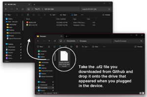
Copy the UF2 file to the device. - A Windows Explorer window may appear with a drive called
RPi-RP2. If it doesn't, open a Windows Explorer window and look for a drive with this name. - Copy the .UF2 file you downloaded to the root folder of the drive that appeared when you plugged in the ZuluSCSI.
- The
RPi-RP2window should close on its own once the copy completes. When the device disconnects on its own, the firmware update process is complete. - Disconnect the USB cables and reattach the ZuluSCSI to its host, if you removed it in step 1.

Troubleshooting
Some simple things to check before you dive deeper:
- Make sure there are no primary/secondary conflicts on the IDE channel that the ZuluSCSI is attached to.
- Make sure that the power connection to the device is secure and attached.
- Try toggling the Cable Select switch. Some BIOSes prefer the device to be one way or the other and there's often little rhyme or reason between even the exact same BIOS on the exact same build across two machines.
For more specific problems, keep reading.
The icon at the left of the problems listed tends to pertain to that particular operating system.

 (as optical drive): The ZuluSCSI doesn't seem to be recognized under MS-DOS.
If you have the ZuluSCSI attached as an optical drive in a system that doesn't natively support the ATAPI protocol, you may have to install a third-party driver to allow DOS to see the drive. This was common for all systems based on 386 processors and earlier, most 486 systems, and some Pentium-based systems.
The simplest solution is to obtain a copy of the Microsoft Windows 98 startup disk, and copy the OAKCDROM.SYS and MSCDEX.EXE files from it to the root folder of your boot drive. Then, modify your CONFIG.SYS and AUTOEXEC.BAT files like this:
CONFIG.SYS
Add this line to the top of the file:
DEVICE=C:\OAKCDROM.SYS /D:MSCD000
AUTOEXEC.BAT
Add this line to the end of the file:
C:\MSCDEX.EXE /D:MSCD000
Reboot the system, and the drive should populate.
Keep in mind that the only DOS-based CD-ROM driver that has been tested to work with the ZuluSCSI at present is the Oak Technology driver (OAKCDROM.SYS) and VIDE-CDD.SYS, the driver that is included on the Microsoft CD-ROM Extensions installation floppy disk.
Other generic drivers, such as the LG (GoldStar) or Adaptec drivers may work, but have not been fully tested.
(as optical drive): The system recognizes the first disc image loaded, but then acts like the drive isn't ready when I change images.
This issue is related to firmware revisions prior to 2024.11.08. Update your device firmware on the Github repo.
If you are unable to update the firmware, there is a workaround that you can use until you are able to do so.
After changing images, try to access the drive. The system will pause for a long moment, and then you should see a message similar to this:
CDR101: Not ready reading drive E:

(A)bort, (R)etry, (F)ail?
Press F to fail the check, and then if it drops back to a command prompt, try to access the drive again and it should present the image as normal.

 (as optical drive): Performing an "eject" command in Windows Explorer doesn't actually cycle to the next image.
This issue is related to firmware revisions prior to 2024.12.10. Update your device firmware on the Github repo.
The workaround for this is to have either the web interface or hardware interface connected and swap images that way. Another workaround is to manually eject the SD card from the ZuluSCSI, add a zero to the beginning of the desired disk image's name, and then reinsert the SD card. The ZuluSCSI will then look for the first image it can load alphabetically, which should be the newly-renamed image.
 (attached to sound card): The ZuluSCSI seems to be working correctly, but it's never detected.
This is a potential hardware configuration issue. Some sound cards, even if they have an actual IDE interface, force themselves to be configured as either the primary or secondary interface in the system and are not configurable. Most sound cards are also capable of recognizing only optical devices, so if you have the ZuluSCSI configured as something other than an optical drive, the card may not recognize the device attached to it. If you want to use the ZuluSCSI as something other than an optical drive, attach it to an IDE port attached to the motherboard or I/O card, as opposed to a sound card.
(with audio DAC board): I have the device attached to my SoundBlaster's CD audio in connector, but I only hear the right channel.
Early SoundBlaster cards (including the Pro and Pro 2) used a different pinout on the CD audio header. Instead of R-G-G-L (right channel, ground, ground, left channel) these cards' pinout was NC-L-G-R (no connect, left, ground, right). You may need to get a different cable.