ZuluIDE Operations Guide
Setting Up Your ZuluIDE
Unboxing
When you first receive your ZuluIDE, depending on the options you ordered, you should receive the following:
- ZuluIDE RP2040 Compact board
- 3D-printed plastic carrier
- 2x ¼" 4-40 screws
- MicroSD card
- Hardware interface board
- Qwiic cable
Board Overview
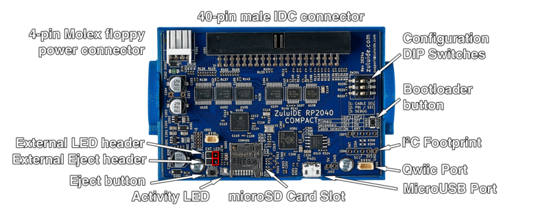
Take a moment to identify the various parts of the board as shown below.

- 4-pin Molex floppy power connector: Run a standard Molex 4-pin power cable to this port. If your system power supply has only the larger style, get an adapter cable to switch it to the smaller size (the same size as that found on a 3½" floppy disk drive).
- 40-pin male IDC connector: Plug your IDE bus cable into this. The connector is keyed, but some IDE cables lack the key, so make sure that the red stripe on the cable lines up with the little arrow embossed into the connector itself.
- Configuration DIP switches: These will set how the ZuluIDE responds when the BIOS requests information from the device.
- Bootloader button: Used during the firmware update process.
- I2C Footprint: Addon boards can attach through this open footprint either by being soldered directly to it or by attaching standard 0.1" header to this footprint.
- Qwiic Port: Addon boards can also attach here through the use of a standard Qwiic I2C cable.