ZuluIDE Operations Guide: Difference between revisions
Jump to navigation
Jump to search
Created page with "== Setting Up Your ZuluIDE == === Unboxing === When you first receive your ZuluIDE, depending on the options you ordered, you should receive the following: * ZuluIDE RP2040 Compact board * 3D-printed plastic carrier * 2x ¼" 4-40 screws * MicroSD card * Hardware interface board * Qwiic cable === Board Overview === Take a moment to identify the various parts of the board as shown below. center|frameless|800x800px * '''4-..." |
No edit summary |
||
| Line 7: | Line 7: | ||
* 3D-printed plastic carrier | * 3D-printed plastic carrier | ||
* 2x ¼" 4-40 screws | * 2x ¼" 4-40 screws | ||
* | * microSD card | ||
* Hardware interface board | * Hardware interface board | ||
* Qwiic cable | * Qwiic cable | ||
| Line 21: | Line 21: | ||
* '''I<sup>2</sup>C Footprint:''' Addon boards can attach through this open footprint either by being soldered directly to it or by attaching standard 0.1" header to this footprint. | * '''I<sup>2</sup>C Footprint:''' Addon boards can attach through this open footprint either by being soldered directly to it or by attaching standard 0.1" header to this footprint. | ||
* '''Qwiic Port:''' Addon boards can also attach here through the use of a standard Qwiic I<sup>2</sup>C cable. | * '''Qwiic Port:''' Addon boards can also attach here through the use of a standard Qwiic I<sup>2</sup>C cable. | ||
* '''MicroUSB Port:''' Used during the firmware update process. Can also be used as a serial monitor to capture debug logs in real time with a second PC. | |||
* '''microSD Card Slot:''' Your SD card with images goes here. | |||
* '''Activity LED:''' Flashes in sync with drive access, also used to indicate failure modes as described later | |||
* '''Eject button:''' Performs a hardware eject for optical drives. Some operating systems will need this after dismounting an image from the system to register that the drive door is closed. | |||
* '''External eject and LED headers:''' If you intend to mount the device internally, but want external access to these, you can use standard 0.1" headers to run an eject button and an LED to a case panel. The red box on the image above indicates the positive pin. | |||
==== Molex power connector ==== | |||
Make sure that your power connection uses a '''3½" floppy power connector,''' not the larger drive connector used on full-size optical drives, hard drives, and the like. | |||
{| class="wikitable" style="margin: auto;" | |||
![[File:Molex 3.5" power connector.png|frameless|135x135px]] | |||
![[File:Molex 3.5" power connector (top).png|frameless|100x100px]] | |||
![[File:Molex 5.25" power connector.png|frameless|117x117px]] | |||
![[File:Molex 5.25" power connector (top).png|frameless|100x100px]] | |||
|- | |||
| colspan="2" |✅ 3½" connector | |||
| colspan="2" |❌ 5¼" connector | |||
|} | |||
==== DIP Switch Configuration ==== | |||
[[File:DIP switches (ZuluIDE).png|center|frameless]] | |||
Set the three DIP switches according to how the device needs to be configured in the host system. | |||
* '''Switch 1:''' Turn IDE Cable Select on or off. ''Most'' systems will work fine with this off, but there are several systems (especially single-board industrial computers) which will use cable-select to determine primary and secondary drives and thus will need it on. If your system hangs during IDE device detection with the ZuluIDE attached to the bus, try turning this switch ON first. | |||
* '''Switch 2:''' Respond as Primary/Master (OFF) or Secondary/Slave (ON). | |||
* '''Switch 3:''' Debug log disable/enable. If this switch is ON, the device will automatically write out a detailed debug log to <code>zululog.txt</code> on the SD card as long as the device is powered on. Additionally, if you have a USB cable plugged into the MicroUSB port on the device with this switch on, it will also print the debug log over the cable via the RP2040's internal serial connection. | |||
Revision as of 12:10, 2 November 2024
Setting Up Your ZuluIDE
Unboxing
When you first receive your ZuluIDE, depending on the options you ordered, you should receive the following:
- ZuluIDE RP2040 Compact board
- 3D-printed plastic carrier
- 2x ¼" 4-40 screws
- microSD card
- Hardware interface board
- Qwiic cable
Board Overview
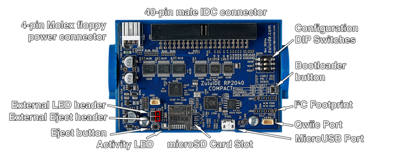
Take a moment to identify the various parts of the board as shown below.

- 4-pin Molex floppy power connector: Run a standard Molex 4-pin power cable to this port. If your system power supply has only the larger style, get an adapter cable to switch it to the smaller size (the same size as that found on a 3½" floppy disk drive).
- 40-pin male IDC connector: Plug your IDE bus cable into this. The connector is keyed, but some IDE cables lack the key, so make sure that the red stripe on the cable lines up with the little arrow embossed into the connector itself.
- Configuration DIP switches: These will set how the ZuluIDE responds when the BIOS requests information from the device.
- Bootloader button: Used during the firmware update process.
- I2C Footprint: Addon boards can attach through this open footprint either by being soldered directly to it or by attaching standard 0.1" header to this footprint.
- Qwiic Port: Addon boards can also attach here through the use of a standard Qwiic I2C cable.
- MicroUSB Port: Used during the firmware update process. Can also be used as a serial monitor to capture debug logs in real time with a second PC.
- microSD Card Slot: Your SD card with images goes here.
- Activity LED: Flashes in sync with drive access, also used to indicate failure modes as described later
- Eject button: Performs a hardware eject for optical drives. Some operating systems will need this after dismounting an image from the system to register that the drive door is closed.
- External eject and LED headers: If you intend to mount the device internally, but want external access to these, you can use standard 0.1" headers to run an eject button and an LED to a case panel. The red box on the image above indicates the positive pin.
Molex power connector
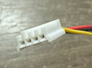
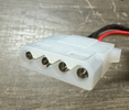
Make sure that your power connection uses a 3½" floppy power connector, not the larger drive connector used on full-size optical drives, hard drives, and the like.

|

|

|

|
|---|---|---|---|
| ✅ 3½" connector | ❌ 5¼" connector | ||
DIP Switch Configuration

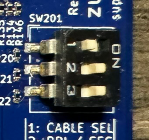
Set the three DIP switches according to how the device needs to be configured in the host system.
- Switch 1: Turn IDE Cable Select on or off. Most systems will work fine with this off, but there are several systems (especially single-board industrial computers) which will use cable-select to determine primary and secondary drives and thus will need it on. If your system hangs during IDE device detection with the ZuluIDE attached to the bus, try turning this switch ON first.
- Switch 2: Respond as Primary/Master (OFF) or Secondary/Slave (ON).
- Switch 3: Debug log disable/enable. If this switch is ON, the device will automatically write out a detailed debug log to
zululog.txton the SD card as long as the device is powered on. Additionally, if you have a USB cable plugged into the MicroUSB port on the device with this switch on, it will also print the debug log over the cable via the RP2040's internal serial connection.